Cross-Flow Heat Exchanger
(Cross-Flow Heat Exchanger)
Key Features:
- For a full understanding of heat exchange by forced convection and measurement of heat transfer
- Enables rapid assessment of heat transfer rates
- Robust, bench-mounting product
- Consists of wind tunnel with fully controllable air flow and heat-exchanger rod matrix
- Separate pre-heated element with built-in thermocouple can take the place of any heat-exchanger rod
- Includes comprehensive, accurate and easy-to-read digital instrumentation on a separate instrumentation unit
- Instrumentation unit also includes a controlled heat source to pre-heat element
Description:
- For comprehensive studies into the principles and performance of heat exchangers. The equipment allows students to quickly assess heat transfer rates by forced convection. They monitor the rate of cooling of a body of known thermal capacity in an air flow.
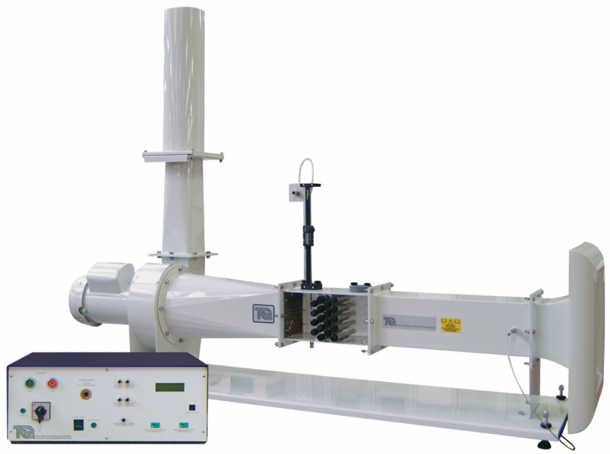
- The apparatus is bench mounting. It is a horizontal wind tunnel with a contraction cone, a working section, a diffuser, a constant speed fan, and an exhaust with silencer. A variable slide valve controls the air flow.
- The working section includes a series of rods arranged in a matrix and at right-angles to the direction of air flow.
- The copper element is of known thermal capacity and includes a built-in thermocouple. Students insert the element, which has been pre-heated to a specific temperature, into the working section at a known air velocity. They measure the time taken for the temperature to drop and determine the heat transfer rate.
- A second thermocouple at the inlet to the wind tunnel measures the temperature of air entering the heat exchanger.
- A Pitot traverse can measure air velocity at any vertical point in the working
section, either before or after the rods - A digital display on the front of the instrumentation unit
allows students to view all experimental data.
Learning Outcomes:
- Determining the pressure losses created by the heat exchange rods and creating a chart of pressure drop against upstream pressure
- Calculating the inlet velocity and the mean velocity through the rods
- Determining the rate at which the heated rod cools down, within a bank of rods and by itself
- Plotting ‘cooling curves’ and using them to find the coefficient of heat transfer (h) for the heated rod at various positions in the heat exchanger
- Determining the velocity distribution (profile) downstream of the rods
- Converting results into dimensionless values (typically using Nusselt, Prandtl and Reynolds equations)
- Comparing results and producing heat transfer coefficient curves
Specifications
Nett dimensions and weight:
• Main part (assembled) – 1530 mm long x 1160 mm high x 400 mm front to back and 55 kg
• Control and Instrumentation unit – 615 mm wide x 220 mm high x 360 mm front to back and 16.5 kg
Heated element:
• Diameter nominally 12.4 mm
• Material: copper
• Built-in thermocouple: K-type
For details see the catalog below: